
Do you want to know more about jitter and how it affects your sound quality? Then keep reading and discover the secrets of digital audio!

If you buy "AuI ConverteR PROduce-RD" (2023/12.x version) from 24 August 2023 to 24 October 2023, you will get free update to version 2024 (13.x) after its release.
- What is jitter audio
- How Jitter Influences Sound and Can We Detect It?
- What Leads to Jitter in Audio?
- Measuring Jitter
- Jitter vs Delay
- Jitter vs Latency
- Understanding Jitter in the Entire Audio System
- The Digital Path from ADC to DAC
- Timing and Jitter in Audio Systems
- Setting the DAC Clock to Avoid Jitter
- Conclusion
- Frequently Asked Questions
What is jitter audio
A device called a digital-to-analog converter transforms digital numbers into a flow of analog electrical signals. These signals should come at regular time intervals, controlled by a timing device. But sometimes, this timing is off, which can twist the sound, as you can see in the image.
Jitter is the irregular timing between these signals.
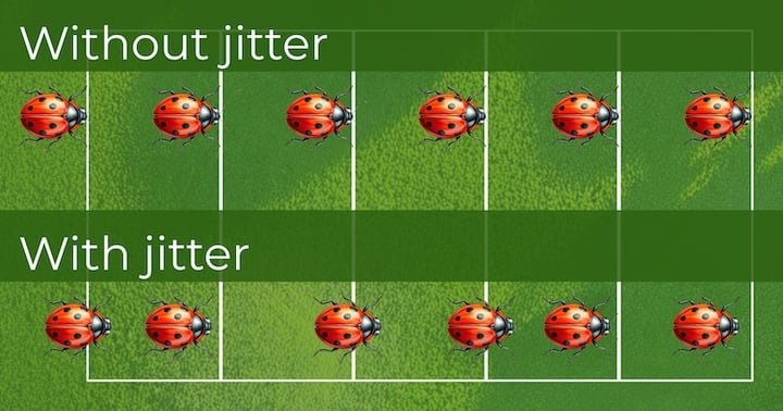
For a simple analogy of jitter, consider the following illustration.
In the image, notice the top line of insects. They march in uniform, touching the lines at the same instant.
Now, look at the image's bottom line of insects. They are not in uniform, touching the lines at separate moments.
This inconsistency in timing is what we call jitter.

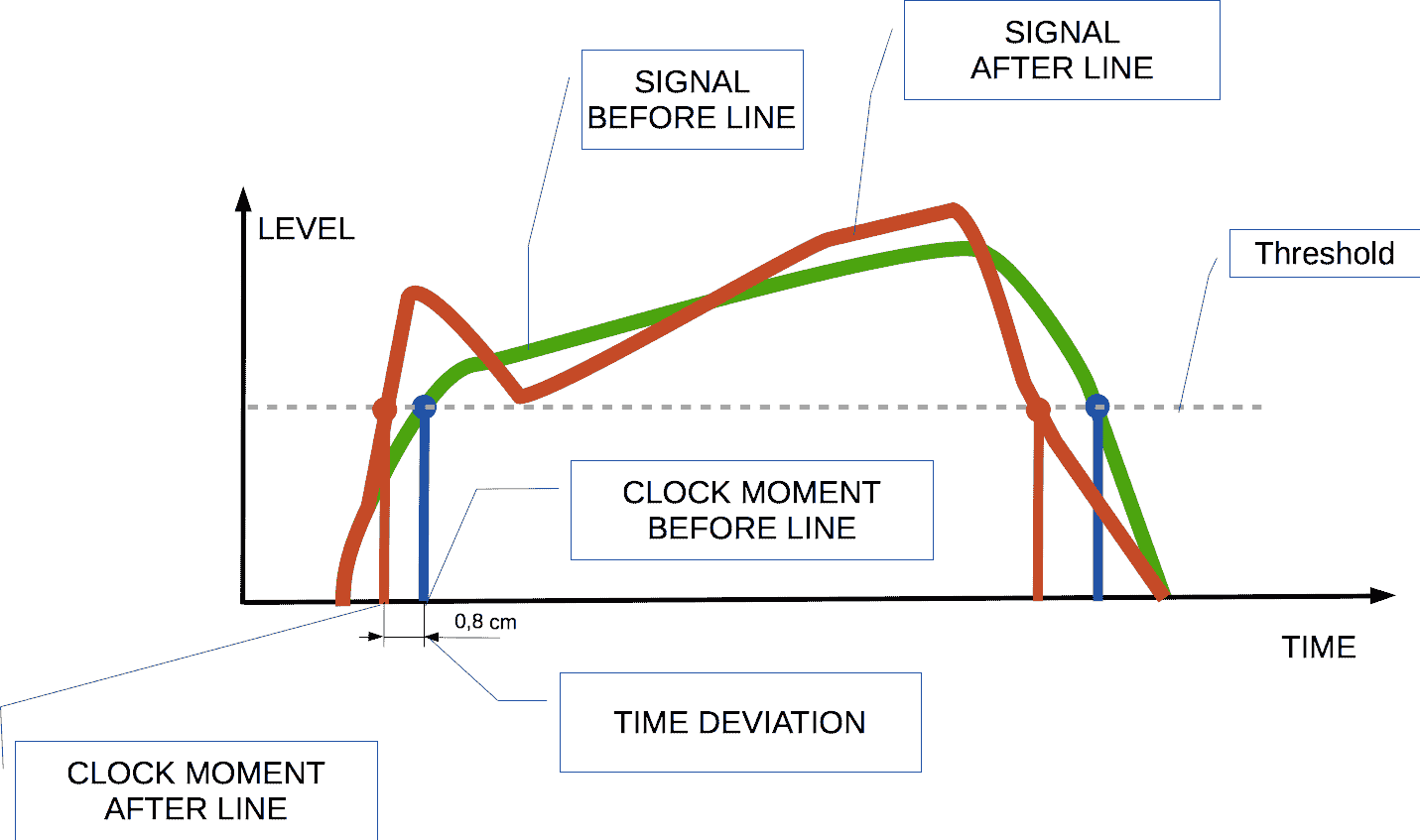
On the top left of the image, there's a green line representing the original digital recording of music.
On the bottom left, we see an attempt to convert that digital recording back to its original sound form.
The dots on the vertical lines show the timing of the signals, which are not steady (jitter). Compare their positions to the positions at the top left of the image. This makes the sound changed, as depicted on the right side of the image.
Back to topHow Jitter Influences Sound and Can We Detect It?
Jitter alters sound form. If we increase jitter on purpose, we might notice extra noise and unwanted sounds.
In everyday situations, jitter affects the analog signal from the digital-to-analog converter. But in current technology, it's usually too minor to detect. It's doubtful we can hear jitter because it blends with other types of noise and distortions from the electronic parts.
Back to topWhat Leads to Jitter in Audio?
Jitter comes from timing issues with the sample clock.
It happens when a digital signal is turned into a binary code during analog input processing.
[Detecting bit values (0/1)]
Here we'll consider clock signal. When sending it through a cable, bits are turned into electrical signals. There are various ways to do this, like using different voltage levels.
Let's look at a amplitude coding:
- If the signal's voltage is above a certain level (shown as a dotted line in the image), it's read as a '1'.
- If it's below that level, it's read as a '0'.
A device sends out these binary signals as electrical pulses. Another device receives them and changes them back into binary code.
The bit changes are read at the exact moments the voltage crosses the threshold.
The sending device creates a signal that's almost like a rectangle.
But as it travels, it can get distorted by noise and other changes.
When the receiver attempts to identify these moments of bit change, slight timing discrepancies may occur.
Next, we'll explore how jitter can enter an audio setup.
Back to top
Measuring Jitter
Jitter changes the sound in unexpected ways. To measure it, we send a smooth, steady tone into the system we're testing.
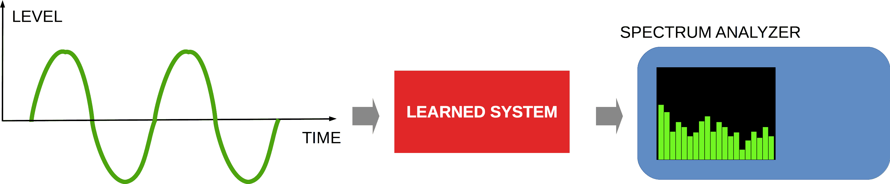
Then, we look for any extra sounds or noise in the system's output.
The type and amount of these extra sounds can vary based on the input. We analyze this by observing the system's response to different tones and volumes.
The image is a simplified illustration, not an actual measurement.
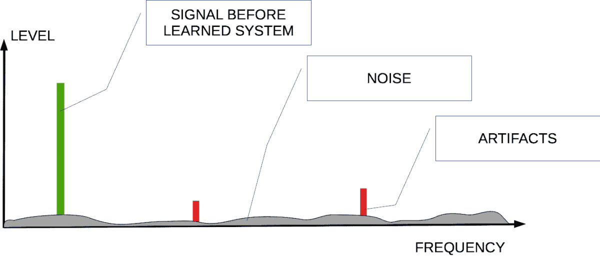
We can evaluate:
- the entire system,
- the digital output of the ADC using a device called a spectrum analyzer,
- the analog output of the DAC using a theoretical smooth tone.
Tests 2 and 3 help us pinpoint where in the system the errors are happening.
Back to top
Jitter vs Delay
Jitter is when there's a change in the timing between sound samples. Delay is when the entire sound is moved later, but the timing between samples stays the same.
Back to top
Jitter vs Latency
Latency is the time it takes for an audio device to process sound, which is usually a fixed delay.
We've already discussed how timing issues can affect digital signals.
Things that can cause timing problems include:
- unstable timing devices,
- noise in the line carrying the digital audio signal.
The timing device has parts that set its frequency and any changes to it.
Fluctuations in the power supply can alter the timing device's frequency.
The power unit can also introduce noise into the system. This noise can change the timing signals.
These changes in timing can be seen in the diagram linked above.
Noise affecting the digital audio line can come from other electronic devices and the environment.
Back to topUnderstanding Jitter in the Entire Audio System
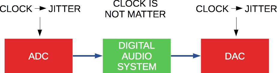
Jitter isn't just a problem with digital-to-analog converters (DACs). It starts with the digital samples we record.
To grasp the issue of jitter, we need to examine the whole process of recording and playback.
- The initial source of jitter is the timing device in the analog-to-digital converter (ADC).
- Next, the digital signal moves through the audio system without any timing mistakes.
- Finally, the digital music signal reaches a DAC, where it's changed back to analog, but with timing errors (see more details below).
Recording music involves taking regular measurements of the sound. If these intervals aren't consistent, it leads to timing errors in the audio samples.
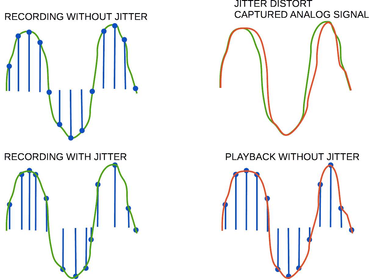
On the top left of the image, the sound is recorded steadily, without jitter.
On the bottom left, the recording has jitter, causing irregularities.
The two recordings show different sample values.
Meaning, when we play back the recordings, the sound waves will be different for each.
Once music is recorded with jitter, we can't fix it because jitter is unpredictable.
Professional recording studios use high-quality equipment, like specialized timing sources (for example, Word Clock [1]), to minimize errors from poor timing.
The Digital Path from ADC to DAC
Let's examine the goal #2 where the digital signal moves through the audio system. In the digital realm, jitter is irrelevant. This is because the timing for the digital signal is exact, like numbers in math.
Delays in processing don't affect the final sound.
Still, if there are hold-ups in the digital processing, it can interrupt the flow of data to the DAC. This isn't a jitter problem, though. More on this below.
Back to topTiming and Jitter in Audio Systems
Let's focus on the goal #3, where the signal reaches the DAC after being in digital form.
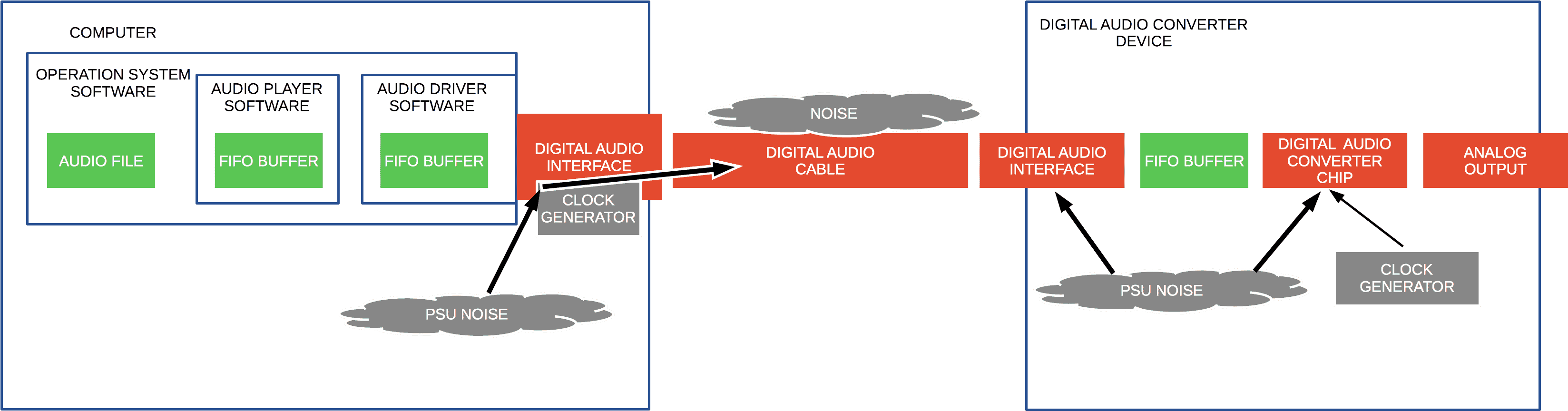
Jitter can be caused by various types of noise entering the digital signal from multiple sources:
- From the computer's power unit to the clock generator of the digital audio interface,
- Through the digital audio interface to the audio cable,
- From the surrounding environment to the DAC's digital audio interface,
- From the DAC's power unit to its digital interface,
- Directly to the DAC chip,
- Within the DAC's own timing generator,
- From the DAC's power unit to its timing generator.
But there's a feature called FIFO buffer that helps to block out jitter.
FIFO stands for "first in, first out." It's a way to store data temporarily where the first piece of data to enter is also the first to leave.
Adding and removing data to and from this buffer doesn't happen at the same time. The times for storing and retrieving data are separate.
This FIFO buffer creates a slight delay, known as latency, which is just the time it takes for data to pass through. This delay can be very short, like seconds or even milliseconds.
Smaller buffers mean less delay. Less delay is crucial for live music systems. For listening at home, a longer delay isn't usually noticeable, unless you're adjusting the sound in real-time.
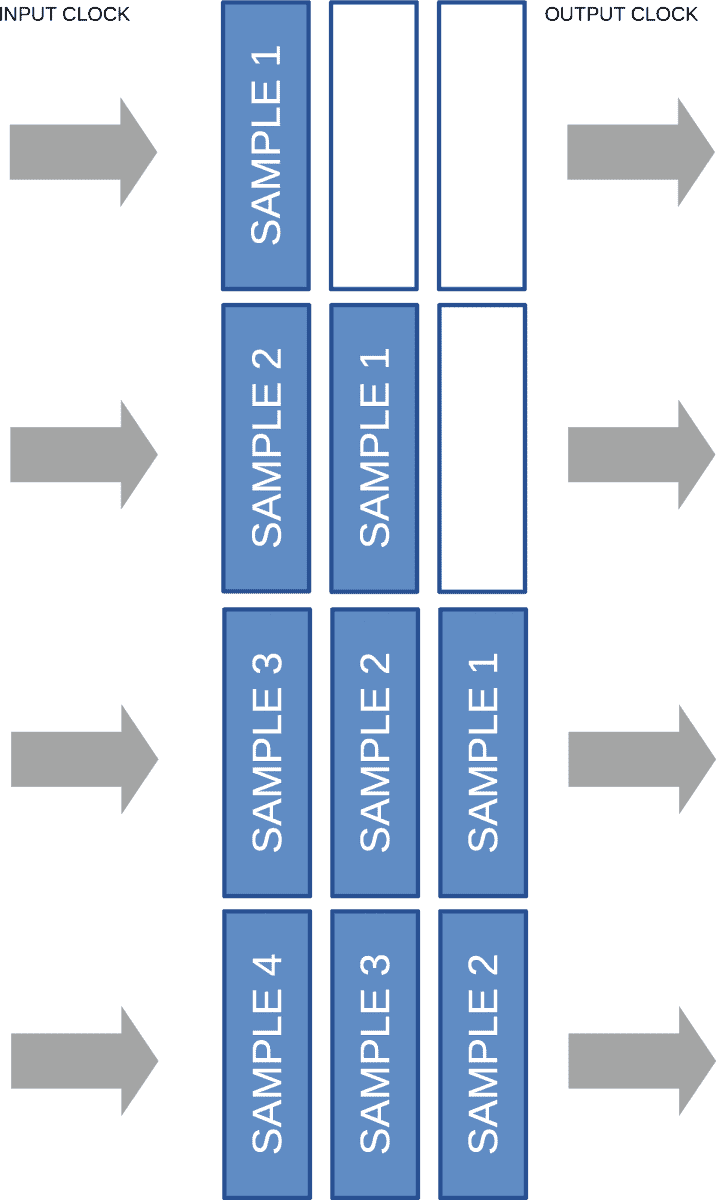
Any jitter before the FIFO buffer doesn't affect the timing after it, because the buffer works independently of the jitter.
So, you don't need to worry about jitter before the FIFO buffer when it comes to the DAC, as shown in the diagram above.
Understanding your audio system's design is key before you can effectively reduce jitter. In many cases, the FIFO buffer can handle small interruptions in the data flow. However, big interruptions that the FIFO can't manage may result in silence or unwanted sounds. This occurs when the buffer runs out of data to convert to sound.
Back to topSetting the DAC Clock to Avoid Jitter
There are three ways to set the DAC clock:
- Using the DAC's digital connection (like SPDIF);
- Using a built-in timing device;
- Using a separate, specialized timing device.
Let's talk about DACs that have a built-in FIFO for incoming audio data.
Setting the clock through the digital connection can introduce jitter from:
- The timing device and power source of the device sending the signal;
- Noise picked up by the signal as it travels through the cable;
- The DAC's power source.
Setting the clock with the DAC's own timing device mainly gets jitter from:
- The device itself;
- The DAC's power source.
Setting the clock with an external timing device can get jitter from:
- The external device and its power source;
- Noise affecting the timing signal as it moves through the cable;
- The DAC's power source.
For home use, the easiest option is to use the DAC's built-in clock. You can select this in the DAC's settings.
But this doesn't always give you the best sound. You should test your audio setup to find the setting that minimizes jitter.
Back to top
Conclusion
- Jitter is only an issue when converting between digital and analog signals.
- It doesn't alter the signal while it's in digital or analog form.
- To check your system's jitter, compare the output with a pure tone.
- A FIFO buffer helps keep different parts of the system from affecting each other with jitter.
- If your DAC has its own clock or uses an external clock generator, jitter before the DAC usually isn't a problem.
- But if your DAC relies on the digital input for timing, you might need to manage jitter before it reaches the DAC.
- The most effective way to handle jitter is to understand your audio system's layout and run some tests.
Frequently Asked Questions
What is jitter noise?
Jitter noise is unwanted sound caused by timing errors in the system's clock. For more information, read the details...
What is jitter in USB?
USB itself doesn't create jitter in the audio data. Jitter happens when audio switches between analog and digital forms. For more information, read the details...
- 64-bit audio processing. Necessity or redundancy >
- What is Audio Converter >
- How to Choose the Best Audio Converter Software >
- What Is Ringing Audio >
- What is dithering audio? >
- Bit-Depth Audio and Harmonic Distortions >
- Audio as Optics >
- What is optimization audio for DAC >
- Where is the Limit of Audio Quality? >
- Power Conditioner for Audio. It's real advantage? >
Audio Basis - articles about audio
Back to top